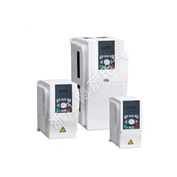
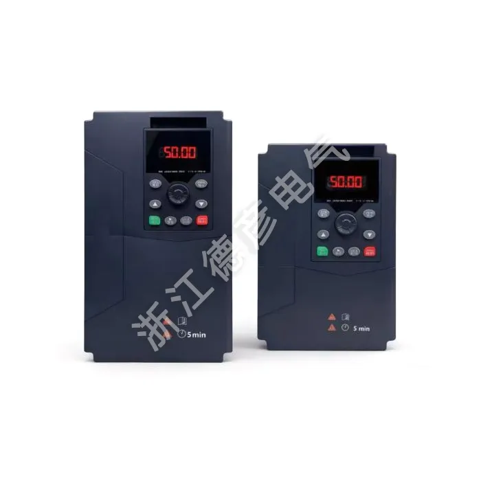
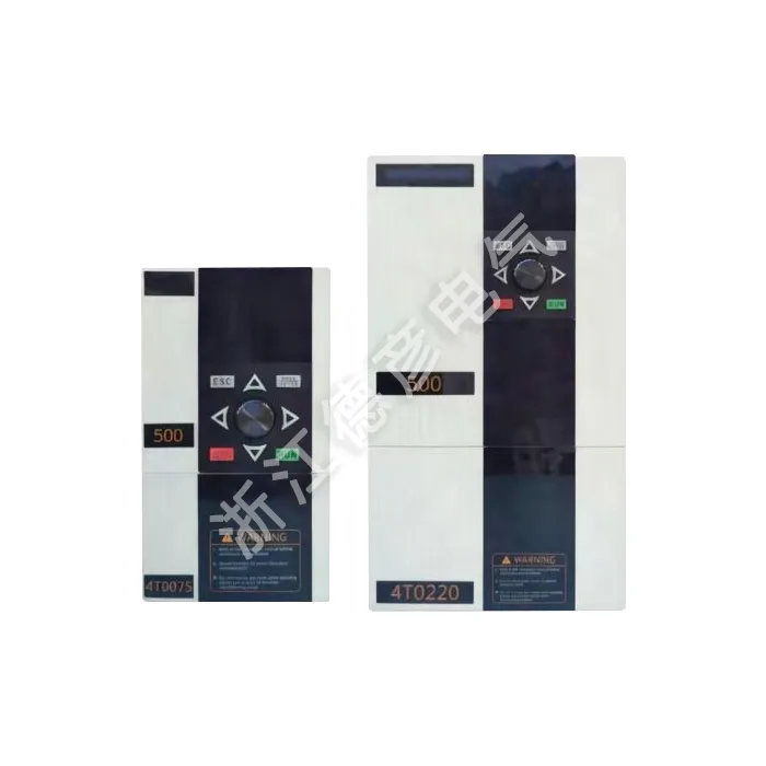
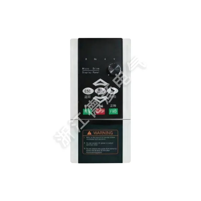
Field‑based engineering feedback repeatedly shows many factory operators add external PID modules alongside standard frequency converters, bringing extra wiring work, additional component failure points and higher total project expense. Deyan Electric, an industrial electrical vendor with years of project experience supplying Europe and North America, engineered the General Purpose Inverter with Built‑in PID Function to resolve exactly this real‑world pain point. Every unit passes factory aging test and full‑load verification before shipment, complying with IEC industry standards. Instead of assembling multiple separate parts, plant engineers and machinery integrators can finish closed‑loop adjustment wholly inside this inverter hardware, streamlining cabinet layout and cutting auxiliary component procurement lists.
Field Pain Points Solved
Most general‑purpose inverters on market require customers to purchase independent PID controllers when they need steady flow, constant pressure or fixed tension control. This creates multiple practical troubles on production floors. This inverter’s native PID capability directly targets those frequent site frustrations:
1. Extra hardware overhead: External PID modules increase BOM cost for machine OEMs; every added device also occupies valuable cabinet installation space. Built‑in PID eliminates these extra component purchases for most conventional closed‑loop applications.
2. Complex signal wiring risk: Cross‑connection between separate controller and inverter introduces potential signal interference, wrong terminal wiring and extra troubleshooting time during commissioning. Process feedback signals connect straight to inverter analog terminals for simpler cabinet wiring layouts.
3. Mismatched response coordination: Timing mismatch between outside PID unit and frequency drive often causes hunting, unstable pressure or swinging flow values. Algorithm runs locally on the inverter main control chip, achieving faster response sync between process feedback and motor frequency output.
For system integrators, machine builders and plant retrofitting projects, removing extra external control hardware lowers total material cost while also reducing possible fault sources on finished equipment.
How PID Works On‑board
The built‑in PID function integrated into the General Purpose Inverter with Built‑in PID Function is not a simplified auxiliary feature; it is a complete process closed‑loop control system implemented within LNC820 DSP firmware. Users feed real‑world physical signals such as pressure sensor, flow transmitter or tension sensor into analog input terminals, and the inverter dynamically adjusts motor output frequency to keep process value near target setpoint.
1. Multi‑source setpoint selection: PID target value can originate from operation panel setting, analog signal input, multi‑speed terminals or RS485 communication. Flexible selection adapts to different operating habits and cabinet control schemes without circuit modification.
2. PID parameter fine‑tuning support: Proportional gain, integral time and differential time parameters are fully adjustable. Operators can tune response speed, suppress overshoot or reduce oscillation according to actual load inertia, whether working on slow‑reacting water pump systems or fast‑changing textile tension scenarios.
3. Protection linkage with drive functions: PID output is tightly coupled with inverter acceleration‑deceleration curves, stall prevention and current limiting. When heavy shock load occurs on‑site, drive protection logic still works normally while PID operation pauses reasonably, avoiding unreasonable frequency output that could damage motor or mechanical structure.
With these integrated capabilities, ordinary on‑site technicians can complete most closed‑loop debugging without learning operation logic of third‑party controller hardware.
Real‑world Application Fit
Built‑in PID does not mean this inverter is only limited to closed‑loop tasks; it can also run as an ordinary V/F drive for open‑loop speed control. Dual‑mode capability expands usable scenarios for machine builders who need one hardware model covering different function requirements across their product lines.
1. Constant pressure water supply & pump stations: Pressure sensor feeds pipe network pressure back to inverter analog port. The General Purpose Inverter with Built‑in PID Function automatically raises or reduces pump motor speed to stabilize pipeline pressure, achieving notable energy‑saving effect for water supply systems.
2. Ventilation and exhaust fan systems: Matches air volume according to workshop pressure or temperature feedback. Instead of manual damper adjustment, motor speed auto‑adjusts, reducing mechanical loss and power consumption of fan equipment.
3. Tension control for textile & wire‑drawing machines: For continuous‑run processing machinery, closed‑loop PID maintains stable material tension to avoid product breakage or uneven finished quality, simplifying mechanical‑type tension‑releasing structures.
4. Packaging and food processing lines: Process flow adjustment for conveying and mixing equipment; one inverter unit handles both motor speed drive and process stabilization for compact machine cabinet design.
From factory renovation projects to brand‑new OEM machine development, this unit cuts hardware list complexity for projects requiring stable physical‑quantity control.
Hardware & Compatibility Notes
While built‑in PID brings large convenience, purchasers still need to match peripheral sensors and understand hardware boundary conditions to get stable closed‑loop performance. The LNC820 series hardware reserves complete signal terminals for PID feedback access.
1. Analog input channel options: Two analog input channels support 0‑10V voltage signal or 0‑20mA current signal, compatible with most common industrial pressure, flow and tension transmitters available on global component markets.
2. Co‑work with other native functions: PID can run together with multi‑speed operation, simple PLC program logic and RS485 communication. Users can build relatively complex automatic workflow without adding small‑size PLC hardware for basic automation needs.
3. Load‑type model selection reminder: G‑type heavy‑duty model suits constant‑torque closed‑loop loads such as textile machinery. P‑type model is recommended for fan and pump square‑law loads. Incorrect model selection will lead to insufficient overload margin even if PID algorithm parameters are properly set.
Correct sensor matching and reasonable model selection allow buyers to make full use of the built‑in PID advantage and prevent unstable closed‑loop performance caused by peripheral side configuration errors.
Quality & Project Delivery
Deyan Electric treats built‑in PID algorithm reliability as one key inspection point during factory testing. Each finished unit will simulate closed‑loop signal feedback inside test bench, verifying PID response together with inverter drive performance before product leaves workshop.
1. Functional aging verification: Not only basic inverter drive functions get tested; PID closed‑loop operation runs continuously during aging procedure to catch firmware‑related abnormality ahead of delivery.
2. Documentation support for PID commissioning: Product manual includes dedicated chapters describing PID terminal wiring, setpoint configuration and parameter tuning guidance, helping overseas engineering teams shorten machine debugging cycle.
3. Flexible batch supply: Power range covers 0.75kW‑400kW. Small sample trial orders and large‑volume project batch supply are both supported for global buyers.
Rigorous pre‑shipment functional check helps machinery OEMs and project contractors reduce unexpected debugging obstacles when devices arrive at end‑user factories.
Procurement & Technical Support
Many overseas purchasers care not only about hardware feature list but also about accessible support when they encounter PID tuning confusion on‑site. Deyan Electric provides corresponding technical resources for buyers selecting this series inverter:
1. Pre‑sales application consultation: Share load condition and target closed‑loop requirement; engineering team can give reference advice about model selection and sensor signal type before you place bulk order.
2. Remote technical assistance: When commissioning hunting, overshoot or output abnormality appears in PID operation, engineering support can guide parameter adjustment remotely to reduce field‑visit cost.
3. Standard factory warranty coverage: Built‑in algorithm function falls under normal product warranty scope; spare‑part stock shortens downtime if hardware replacement becomes necessary.
Complete support chain lowers overall project risk for integrators applying built‑in PID closed‑loop solutions on‑site.
FAQ
Q: Do I still need an external PID controller after choosing this inverter?
A: For most conventional pressure, flow and tension closed‑loop applications, external PID hardware is no longer required. Sensor feedback signal connects directly to inverter analog input terminals. If your project involves extremely complex multi‑loop interlock logic, you may still need independent PLC system for upper‑level logic processing.
Q: What sensor signal types work with the built‑in PID?
A: Analog terminals accept 0‑10V voltage signal and 0‑20mA current signal, matching mainstream industrial transmitters. Confirm your sensor output signal type before wiring to avoid signal reading failure.
Q: Can built‑in PID run together with RS485 communication function?
A: Yes. You can set PID target value via RS485 bus, and read back process feedback value and running status over communication port. This fits cabinet systems controlled by host monitoring equipment.
Q: Why does PID output keep oscillating even after hardware wiring is correct?
A: Oscillation usually relates to PID gain parameters or mechanical system inertia. Reduce proportional gain or increase integral time; also check whether sensor installation location brings measurement fluctuation. Adjust step‑by‑step according to manual tuning guidance.
Nameplate Reference
|
MODEL:
|
LNC820‑4T0040GB/4T0055PB
|
|
POWER:
|
4KW 9A/5.5KW 13A
|
|
INPUT:
|
3PH AC380V 50HZ/60HZ
|
|
OUTPUT:
|
3PH AC0V‑380V 0HZ‑500HZ
|
|
S.N:
|
Barcode
|
Full Technical Specification
|
Item
|
Specification
|
|
Basic functions
|
Output frequency
|
0‑500Hz
|
|
Carrier frequency
|
0.8kHz~12kHz the carrier frequency can be automatically adjusted according to the load characteristics
|
|
Frequency resolution
|
0.01Hz
|
|
Control mode
|
V/F control
|
|
Torque characteristics
|
With torque compensation and slip compensation,starting torque: G‑type machine 0.5Hz/150%,P‑type machine 0.5Hz/100%
|
|
Torque boost
|
Automatic torque boost;Manual torque boost 0.1%~30.0%
|
|
Overload capacity
|
G‑type machine:150%of rated output current for 60S P‑type machine:130%of rated output current for 60S
|
|
Speed regulation range
|
1:100
|
|
Speed stability accuracy
|
±1%
|
|
Automatic voltage regulation(AVR)
|
When the grid voltage changes,it can automatically maintain a constant output voltage
|
|
Over‑voltage and over‑current stall control
|
Automatically limits the current and voltage during operation to prevent frequent over‑current and over‑voltage tripping
|
|
Fast current‑limiting function
|
Minimizes over‑current faults to protect the normal operation of the frequency converter
|
|
V/F curve
|
Four modes:linear type;multi‑point type;complete V/f separation;incomplete V/f separation
|
|
Acceleration and deceleration curves
|
Linear or S‑curve acceleration and deceleration modes;four acceleration and deceleration times; acceleration and deceleration time range:0.1~6500.0s
|
|
DC braking
|
DC braking frequency:0.00Hz~maximum frequency,braking time:0.0s~36.0s, braking action current value:0.0%~100.0%
|
|
Simple PLC,multi‑ speed operation
|
Jog frequency range:0.00Hz~50Hz;jog acceleration and deceleration time:0.0s~6500.0s
|
|
Jog control
|
Up to 16‑speed operation can be achieved through the built‑in PLC or control terminals
|
|
Built‑in PID
|
It can easily implement a process‑control closed‑loop control system
|
|
Operating characteristics
|
Operating command channel
|
Three channels:given by the operation panel,given by the control terminals,given by the serial communication port.It can be switched in various ways
|
|
Frequency source
|
Ten frequency sources:given by panel knob,given by operation panel,given by analog voltage, given by analog current,given by RS485 communication,multi‑speed,PID,simple PLC, which can be switched in various ways
|
|
Auxiliary frequency source
|
Ten auxiliary frequency sources.It can flexibly achieve auxiliary frequency fine‑tuning and frequency synthesis
|
|
Input terminals
|
Six digital input terminals,one of which can be used as a high‑speed pulse input. Two analog input channels,AI1:input range 0~+10V,AI2:input range 0~+10V/0‑20mA
|
|
Display and keyboard operation
|
Output terminals
|
One high‑speed pulse output terminal,outputting square‑wave signals from 0kHz~50kHz which can realize the output of physical quantities such as set frequency and output frequency. One digital output terminal. One relay output terminal. Two analog output terminals,AO2:0V~10V, AO1:0V~10V/0‑20mA,which can indicate output frequency/current/voltage/frequency command/ speed/power factor signal output
|
|
LED display
|
It is equipped with 8 function keys,a 5‑digit 7‑segment LED,and 5 status LED indicators. It can perform forward rotation,reverse rotation,reset,stop,jog,as well as parameter setting and display
|
|
Protection characteristics
|
Protection function
|
Motor short‑circuit detection upon power‑on,output phase‑loss protection,over‑current protection,over‑voltage protection,under‑voltage protection,over‑heat protection,overload protection,etc
|
|
Environment
|
Application place
|
Indoors,not directly exposed to sunlight,free from dust,corrosive gases,flammable gases,oil mist, water vapor,dripping water or salt,etc
|
|
Altitude
|
Less than 1000m
|
|
Ambient temperature
|
‑10℃~+40℃(When the ambient temperature is between 40℃~50℃,derating operation is required)
|
|
Humidity
|
Less than 95%RH,without water droplet condensation
|
|
Vibration
|
Less than 5.9m/s²(0.6g)
|
|
Storage temperature
|
‑20℃~+60℃
|