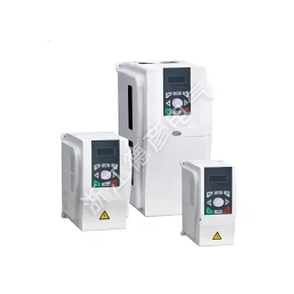
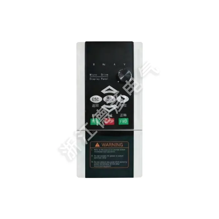
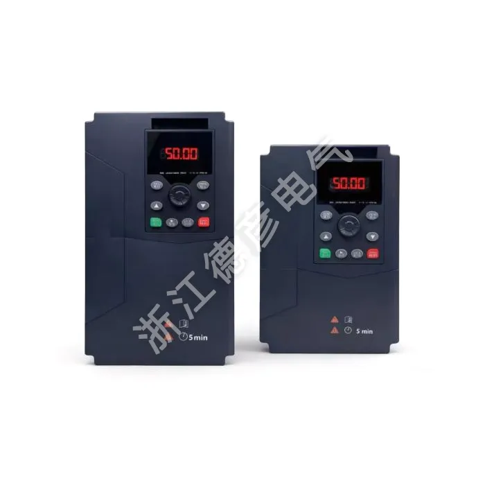
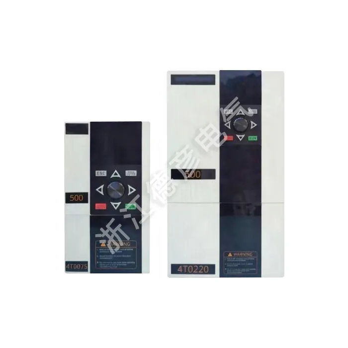
Many system integrators learn from on‑site deployments that not every motor application demands vector‑level dynamic torque response. The Variable Frequency Inverter with V/F Control Mode executes open‑loop voltage‑to‑frequency proportional adjustment, maintaining motor magnetic flux across varying operating speeds without encoder feedback or complex motor parameter identification. This LNC820 unit supports multiple customizable V/F curve profiles, works well with mixed‑brand standard induction motors, and cuts pre‑installation preparation work. For projects running dozens of drives in one cabinet build, its forgiving parameter requirements reduce on‑site support workload significantly.
How V/F Open‑Loop Control Behaves Under Real‑World Operating Conditions
V/F control works by scaling output voltage synchronously alongside output frequency, preserving consistent magnetic flux inside the motor stator. Its practical limits and behavioural traits rarely appear on brief datasheet summaries but directly shape project reliability:
1. No mandatory motor auto‑identification routine: Unlike vector‑mode inverters, you can commission most standard motors without running static or rotating motor tuning. This is a major advantage when swapping spare motors on‑site where nameplate data may be incomplete or partially illegible.
2. Low‑speed torque naturally drops without boost settings: At frequencies below roughly 10‑15Hz, raw V/F output yields reduced motor torque. Built‑in torque boost parameters compensate for this shortfall for light‑to‑moderate starting loads; heavy low‑speed starting loads remain outside its intended operating envelope.
3. Speed drift occurs under fluctuating load: Being open‑loop architecture, actual motor slip increases as mechanical load rises. Typical open‑loop speed deviation sits within 1‑3% without pulse encoder feedback, acceptable for fan, pump, simple conveyor applications, but unsuitable for high‑precision synchronisation tasks.
4. Supports custom V/F curve shaping for special loads: Users can configure linear, squared‑law, and user‑defined broken‑line V/F profiles. Squared V/F preset optimises energy performance for fan‑pump square‑torque loads; linear V/F fits general constant‑torque light‑duty machinery.
Understanding these native characteristics helps integrators avoid inappropriate specification where V/F control is mismatched against application requirements.
Key Selection Factors When Sourcing V/F‑Mode Drives For OEM & System Builds
Procurement teams frequently compare pure hardware specifications, yet several application‑oriented parameters heavily influence long‑term field uptime for Variable Frequency Inverter with V/F Control Mode units:
1. Flexible V/F curve editing capability: Confirm whether the unit provides multi‑segment broken‑line V/F tables, not only fixed linear and square curves. Custom curve settings resolve motor over‑magnetisation or under‑torque issues when driving ageing or non‑standard induction motors.
2. Torque‑boost granularity: Coarse‑stepped boost adjustment makes on‑site fine‑tuning difficult. Smooth adjustable torque boost allows technicians to dial in just enough low‑frequency voltage, preventing motor saturation, over‑heating and nuisance over‑current trips at startup.
3. Compatibility with long motor cable runs: Cabinets installed far away from driven motors generate reflected‑wave voltage spikes. This model includes parameter optimisations for long‑cable scenarios to mitigate insulation stress on motor windings without adding extra output reactors in many ordinary cases.
4. I/O terminal mapping flexibility: For volume OEM cabinet production, freely‑assignable digital and analogue terminals reduce internal wiring modification work across different machine variants, streamlining assembly workflow.
Ignoring these practical points can create avoidable on‑site troubleshooting even if kW rating matches motor nameplate perfectly.
Typical Applications That Get Maximum Value From V/F‑Mode Open‑Loop Drives
This inverter delivers its best cost‑performance balance for machinery that does not demand tight speed holding or heavy low‑speed starting torque. These are recurring project types from our global OEM partners:
1. HVAC air‑handling units and centrifugal ventilation fans: Square‑law V/F profile optimises energy consumption as airflow demand changes day‑to‑day. No high dynamic torque response required, stable open‑loop operation fits most building ventilation retrofits.
2. General‑purpose water and fluid transfer pumping systems: Constant‑pressure water supply with built‑in PID works alongside V/F regulation. Suited for booster pumps, circulation pumps and wastewater transfer pumps without heavy starting blockage risks.
3. Light‑duty material‑handling conveyors and simple processing lines: Flat‑belt conveyors, sorting tables and light agitators where load variation stays moderate. Smooth soft‑start reduces mechanical shock on belts, chains and gearboxes.
4. Small‑to‑medium processing auxiliary machinery: Mixers, simple rotary drums, cooling tower drives and workshop auxiliary equipment. Where operators primarily need smooth speed variation rather than precise closed‑loop speed locking.
Applications involving hoisting, heavy‑start positive‑displacement blowers, high‑precision web synchronisation should opt for vector‑control capable inverters instead, even at higher component cost.
Common Field Mis‑configuration & Practical Work‑Around Guidance
Most service calls for V/F‑mode inverters do not stem from hardware defects; they come from mis‑set V/F curves, incorrect torque boost values or misjudged application boundaries. These notes draw from accumulated global support tickets:
1. Excessive torque boost triggering over‑current at low frequency: Over‑setting voltage boost saturates motor magnetic circuit. Reduce boost percentage, and if low‑speed torque remains insufficient, consider upsizing inverter current rating rather than cranking boost parameters higher.
2. Motor overheating running continuously below 15Hz: Standard self‑cooled motors lose cooling airflow at low rpm. Add external motor blower fans or set minimum‑frequency limits inside drive parameters to avoid sustained ultra‑low‑frequency running conditions.
3. Motor over‑voltage and buzzing noise at high‑frequency operation: Mismatched custom V/F curve pushes output voltage above motor rated voltage. Double‑check end‑point voltage setting matches motor nameplate voltage rating.
4. Expecting V/F mode to handle large sudden load shocks: Open‑loop V/F cannot instantly compensate sharp load surges. If your process sees frequent abrupt load spikes, re‑evaluate whether vector control hardware is genuinely required for that machine station.
Documenting V/F curve and boost settings per‑machine during commissioning greatly simplifies later maintenance and spare‑drive replacement jobs.
Production Validation & OEM‑Oriented Commercial Support
Every Variable Frequency Inverter with V/F Control Mode completes dedicated V/F‑profile functional testing during factory ageing cycle, not just generic no‑load motor spin‑up checks:
1. Multi‑V/F‑curve bench validation: Test bench verifies linear, squared‑law and broken‑line custom V/F profiles, torque‑boost response, and analogue‑reference speed input behaviour before shipment, catching parameter‑related firmware anomalies early.
2. Documentation tailored for cabinet builders: User manual includes dedicated sections covering V/F curve adjustment, torque boost tuning and long‑cable installation advice, helping OEM technical teams standardise commissioning procedures across multiple projects.
3. Flexible volume logistics: Full power range from 0.75kW‑400kW in stock. Support sample evaluation orders, mid‑size cabinet‑builder batches and large‑scale project bulk deliveries.
4. Parameter template sharing support: For high‑volume OEM partners, we can assist with pre‑loading standard application parameter sets at factory, cutting repetitive on‑site configuration labour.
Application‑focused factory testing reduces debugging risk especially for integrators deploying large fleets of open‑loop V/F drives.
FAQ
Q: Can V/F‑mode inverter run heavy‑start‑up load equipment?
A: Limited. Torque‑boost settings offer partial low‑frequency torque improvement, yet V/F open‑loop architecture cannot match vector‑mode low‑speed heavy‑torque output. For roots blowers, hoists and high‑inertia machinery with severe starting resistance, select vector‑capable models instead.
Q: Do I need to run motor static auto‑tune for V/F‑mode operation?
A: Not mandatory for standard induction motors. Basic V/F operation works purely off nameplate frequency‑voltage values. Motor auto‑tune brings minimal performance gain under V/F mode, unlike vector control workflows where tuning is critical.
Q: Can I switch between linear V/F and squared V/F curve on‑site?
A: Yes. Parameter menu lets technicians toggle between curve profiles. Squared‑law V/F is optimised for fan‑pump square‑torque loads; linear V/F fits light‑duty constant‑torque equipment.
Q: What causes motor loud humming noise after setting custom V/F curve?
A: Most often caused by magnetic saturation from incorrect voltage‑frequency ratio. Reduce torque‑boost value or revise break‑point voltage inside custom V/F table; also check carrier‑frequency adjustment options for acoustic noise improvement.
Product Comparison Table: V/F Control vs Sensorless Vector Control
|
Performance Item
|
V/F Control Mode
|
Sensorless Vector Control
|
|
Motor auto‑tune requirement
|
Not required
|
Recommended, often mandatory
|
|
Low‑speed starting torque
|
Moderate (depends on torque boost)
|
High, stable low‑rpm torque output
|
|
Open‑loop speed accuracy
|
±1~3% slip drift exists
|
Better speed holding under load change
|
|
Project hardware cost level
|
Cost‑optimized
|
Higher component cost
|
|
Best‑fit use‑cases
|
Fan, pump, light‑duty conveyor
|
Heavy start, speed‑critical machinery
|
Nameplate Reference
|
MODEL:
|
LNC820‑4T0040GB/4T0055PB
|
|
POWER:
|
4KW 9A/5.5KW 13A
|
|
INPUT:
|
3PH AC380V 50HZ/60HZ
|
|
OUTPUT:
|
3PH AC0V‑380V 0HZ‑500HZ
|
|
S.N:
|
Barcode
|
Full Technical Specification
|
Item
|
Specification
|
|
Basic functions
|
Output frequency
|
0‑500Hz
|
|
Carrier frequency
|
0.8kHz~12kHz the carrier frequency can be automatically adjusted according to the load characteristics
|
|
Frequency resolution
|
0.01Hz
|
|
Control mode
|
V/F control (Linear, Square‑law, Multi‑segment broken‑line V/F)
|
|
Torque characteristics
|
Adjustable torque boost, starting torque depends on V/F curve setting; G‑type machine 0.5Hz/150%, P‑type machine 0.5Hz/100%
|
|
Torque boost
|
Automatic torque boost;Manual torque boost 0.1%~30.0%
|
|
Overload capacity
|
G‑type machine:150%of rated output current for 60S P‑type machine:130%of rated output current for 60S
|
|
Speed regulation range
|
1:100
|
|
Speed stability accuracy
|
±1%(Open‑loop V/F mode)
|
|
Automatic voltage regulation(AVR)
|
When the grid voltage changes,it can automatically maintain a constant output voltage
|
|
Over‑voltage and over‑current stall control
|
Automatically limits the current and voltage during operation to prevent frequent over‑current and over‑voltage tripping
|
|
Fast current‑limiting function
|
Minimizes over‑current faults to protect the normal operation of the frequency converter
|
|
V/F curve
|
Linear type;Square‑law type;Multi‑segment user‑defined broken‑line V/F
|
|
Acceleration and deceleration curves
|
Linear or S‑curve acceleration‑deceleration; four groups of time settings; range:0.1~6500.0s
|
|
DC braking
|
DC braking frequency:0.00Hz~maximum frequency,braking time:0.0s~36.0s, braking action current value:0.0%~100.0%
|
|
Simple PLC,multi‑ speed operation
|
Jog frequency range:0.00Hz~50Hz;jog acceleration‑deceleration time:0.0s~6500.0s
|
|
Jog control
|
Up to 16‑speed operation can be achieved through the built‑in PLC or control terminals
|
|
Built‑in PID
|
It can easily implement a process‑control closed‑loop control system
|
|
Operating characteristics
|
Operating command channel
|
Three channels:given by the operation panel,given by the control terminals,given by the RS485 communication port.Various switching modes supported
|
|
Frequency source
|
Ten frequency sources:panel knob,operation panel,analog voltage, analog current,RS485 communication,multi‑speed,PID,simple PLC, etc.
|
|
Auxiliary frequency source
|
Ten auxiliary frequency sources,support frequency superposition and fine‑tuning
|
|
Input terminals
|
Six digital input terminals,one supports high‑speed pulse input. Two analog input channels,AI1:0~+10V,AI2:0~+10V/0‑20mA
|
|
Display and keyboard operation
|
Output terminals
|
One high‑speed pulse output terminal;One digital output terminal;One relay output terminal. Two analog output terminals,AO2:0V~10V, AO1:0V~10V/0‑20mA,monitoring frequency/current/voltage/speed/power‑factor etc.
|
|
LED display
|
8 function keys,5‑digit 7‑segment LED,multi‑status indicator lamps;support forward/reverse/reset/jog/parameter setting
|
|
Protection characteristics
|
Protection function
|
Motor short‑circuit detection upon power‑on,output phase‑loss protection,over‑current protection,over‑voltage protection,under‑voltage protection,over‑heat protection,overload protection,etc
|
|
Environment
|
Application place
|
Indoors;avoid direct sunlight,dust,corrosive gas,flammable gas,oil mist,water splash and salt‑mist environment
|
|
Altitude
|
Derating required above 1000m elevation
|
|
Ambient temperature
|
‑10℃~+40℃(Derate when operating between 40℃~50℃)
|
|
Humidity
|
Less than 95%RH,non‑condensing
|
|
Vibration
|
Less than 5.9m/s²(0.6g)
|
|
Storage temperature
|
‑20℃~+60℃
|