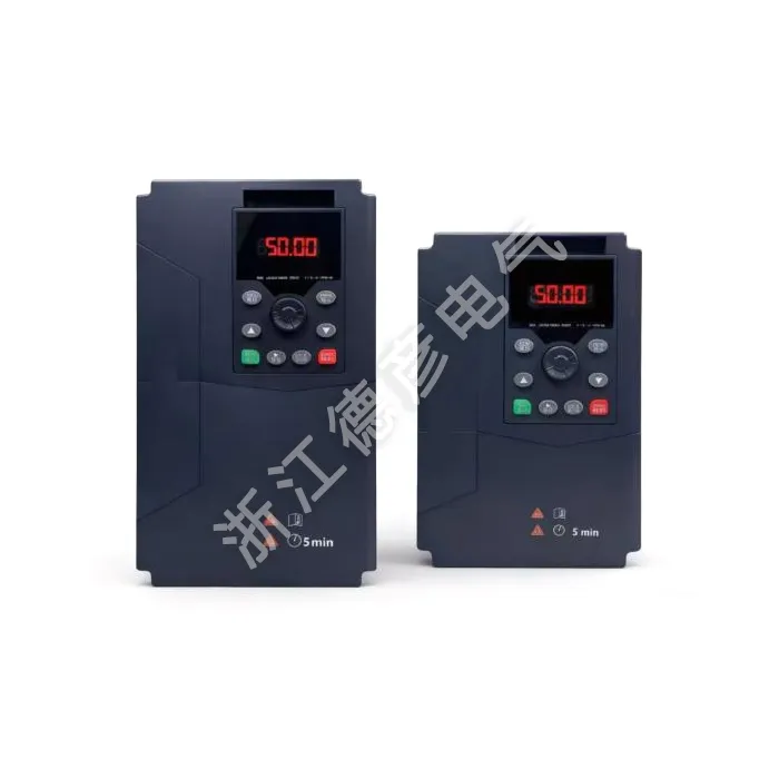
Inverter Drive for CNC Machining Center Equipment
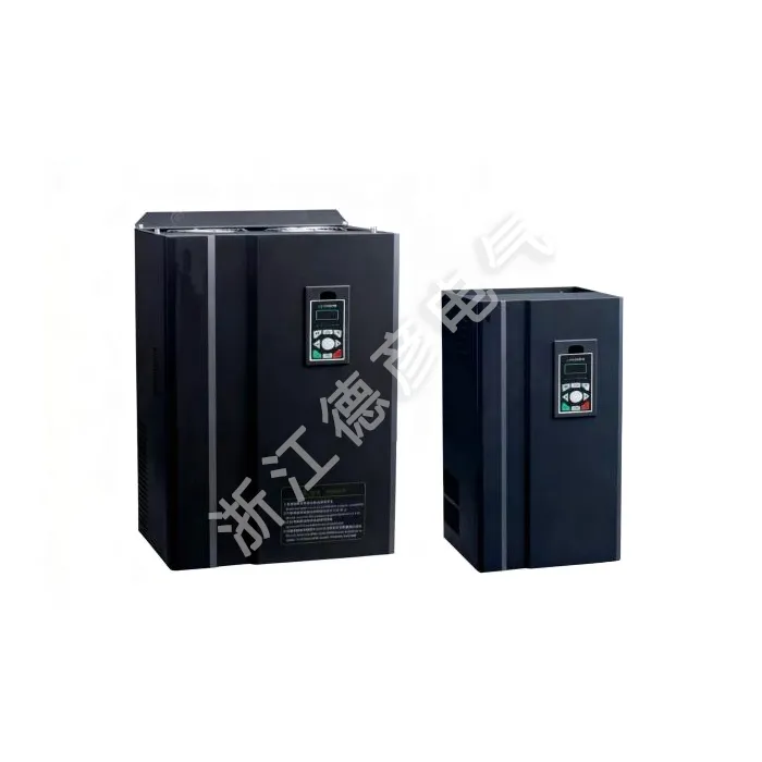
Walk into any CNC machining workshop, and you will hear the same complaints. The spindle speed drifts when the cutter engages a heavy cut, leaving chatter marks on expensive workpieces. The drive trips during a deep pass, forcing a reset and scrapping the part. Commissioning a new drive takes half a day because the parameter structure is unintuitive. These are not hypothetical concerns—they are daily friction points that cost time, money, and operator patience. The Inverter Drive for CNC Machining Center Equipment from Deyan Electric was designed with these exact problems in mind. It is not a repurposed pump drive. It is a purpose-built motor control solution, leveraging proven vector control architecture and industrial-grade power components, specifically tuned for the demands of spindle and axis control on machining centers.
Beyond just spindle speed
In CNC machining, the number on the speed display matters far less than how consistently that speed is maintained under actual cutting loads. When a cutter enters a corner or engages a varying depth of cut, the load on the spindle changes instantly. If the drive cannot compensate in real time, speed drops, surface finish suffers, and tool wear accelerates. This is the fundamental difference between a drive that merely runs a motor and one that truly controls a machining process.
What the Inverter Drive for CNC Machining Center Equipment delivers in practice:
● Speed stabilization accuracy: In closed-loop vector control (FVC) mode with encoder feedback, the drive holds ±0.02% speed accuracy. For a spindle running at 10,000 RPM, that is a deviation of only 2 RPM—imperceptible to the cut and invisible on the finished surface.
● Starting torque that handles inertia: Heavy spindles and large chucks have high rotational inertia. This drive delivers 150% starting torque at 0.5Hz in SVC mode, ensuring smooth acceleration without oversizing the motor or suffering from startup stalls.
● Open-loop capability when feedback is unavailable: Not every spindle motor has an encoder. In SVC mode, the drive still achieves ±0.5% speed accuracy, which is significantly better than standard V/F control and perfectly adequate for many general-purpose machining operations.
When you put these capabilities together, the outcome is predictable: consistent surface finishes across entire production runs, extended insert life because the cutter is not subjected to speed fluctuations, and the confidence to push feed rates higher without worrying about process variability. You spend less time inspecting parts and more time making chips.
Eliminating chatter marks
Chatter is the machinist's oldest adversary. It shows up as visible vibration marks on the workpiece, creates unpleasant noise, and can even damage spindle bearings over time. One of the most common causes of chatter is mechanical resonance—when the spindle speed coincides with the natural frequency of the machine structure or the tool-holder system. Many drives simply ignore this, leaving the operator to manually avoid certain RPM ranges, which is not always practical when optimal cutting speeds fall within those resonant bands.
How this drive gives you direct control over resonance:
● Two-stage frequency hopping: You can program up to two distinct frequency bands to be skipped automatically. If your machining center has known resonance points at, say, 420Hz and 580Hz, the drive will jump over these frequencies during acceleration and deceleration, avoiding the chatter zone entirely without any operator intervention.
● Automatic torque boost: When the load increases suddenly—such as when a cutter engages a workpiece—the drive automatically boosts torque to prevent speed drop. This stops the speed dip that often triggers resonant vibrations, keeping the cut smooth.
● Slip compensation: Motor slip changes with load. The drive compensates for this dynamically, maintaining the commanded speed even as the load varies, which further stabilizes the cut and reduces vibration tendencies.
With these features working in tandem, you can run at optimal cutting speeds without fear of resonance-induced defects. This means better surface quality, reduced secondary finishing operations, and less wear on your spindle assembly—a direct contribution to lower operating costs and higher throughput.
Surviving heavy overloads
Roughing passes are the backbone of efficient metal removal, but they also represent the greatest stress on a spindle drive. When the cutter engages a full-width cut in stainless steel or titanium, the torque demand spikes dramatically. Many drives are rated for nominal current but trip at the first sign of an overload, interrupting the cut and potentially damaging the workpiece. The question is not whether your drive can run at 100% load—it is whether it can handle the 150% spikes that occur during real-world machining.
Built-in margins that make a difference:
1. Overload capacity: This drive is rated for 150% of its nominal output current for a full 60 seconds. This is not a peak value for a few milliseconds; it is a sustained capability that gives you genuine headroom during heavy intermittent cuts.
2. Fast current-limiting function: Instead of tripping immediately during a transient overload, the drive actively limits the current while still delivering maximum torque. This prevents nuisance faults and allows the cut to complete, avoiding costly restarts.
3. Automatic voltage regulation (AVR): Grid voltage fluctuates, especially in industrial plants with heavy machinery. The AVR function maintains a constant output voltage to the motor regardless of input dips, ensuring that a momentary brownout does not translate into a spindle stall.
4. Built-in braking unit (22kW and below): During rapid deceleration, regenerative energy can overheat the drive. For models up to 22kW, an internal braking unit is included, saving panel space and reducing external component costs. Braking time and current are fully configurable to match your specific deceleration requirements.
Combined, these features mean that your machining center can handle the toughest roughing cycles without interruption. You eliminate the frustration of mid-cut trips, reduce scrapped parts, and protect your spindle motor from thermal stress. It is reliability engineered for the real world, not just the datasheet.
Key parameters for your spindle selection
Beyond the functional benefits, procurement engineers and maintenance leads need to verify that the drive's electrical and environmental specifications align with their machine's requirements. The table below consolidates the critical technical data for the Inverter Drive for CNC Machining Center Equipment, all derived from actual factory test standards, so you can cross-check compatibility with your existing spindle motor and plant conditions.
|
Power Range
|
0.75KW~5.5KW (220V), 0.75KW~750KW (380V)
|
|
Output Frequency
|
0~500Hz
|
|
Carrier Frequency
|
0.8kHz~12kHz (automatically adjustable based on load characteristics)
|
|
Output Frequency Resolution
|
Digital setting: 0.01Hz; Analog setting: Maximum frequency × 0.025%
|
|
Control Modes
|
Open-loop vector control (SVC), V/F control, Closed-loop vector control (FVC)
|
|
Starting Torque
|
150% at 0.5Hz (SVC)
|
|
Torque Control Accuracy
|
SVC: Above 5Hz ±5%; FVC: ±3%
|
|
Speed Regulation Range
|
1:200 (SVC), 1:1000 (FVC)
|
|
Speed Stabilization Accuracy
|
±0.5% (SVC), ±0.02% (FVC)
|
|
Overload Capacity
|
150% of rated output current for 60 seconds
|
|
V/F Curve
|
Four modes: linear, multi-point, complete V/f separation, incomplete V/f separation
|
|
Acceleration/Deceleration Time
|
0.1~6500.0s (linear or S-curve)
|
|
DC Braking
|
Braking frequency: 0.00Hz~maximum frequency; Braking time: 0.0s~36.0s
|
|
Digital Inputs
|
5 digital input terminals (one configurable as high-speed pulse input)
|
|
Analog Inputs
|
2 analog input channels: AI1 (0~+10V), AI2 (0~+10V / 0~20mA)
|
|
Output Terminals
|
1 high-speed pulse output (0kHz~50kHz), 1 digital output, 1 relay output, 2 analog outputs (0V~10V / 0~20mA)
|
|
Communication
|
RS485 with Modbus protocol (standard)
|
|
Braking Unit
|
Built-in for 22kW and below
|
|
Optional Cards
|
IO expansion card, communication card (isolated type), PG card
|
|
Encoder Support
|
Differential, open-drain, UVW, resolver
|
|
Ambient Temperature
|
-10℃~+40℃ (derating required for 40℃~50℃)
|
|
Altitude
|
Less than 1000m
|
|
Humidity
|
Less than 95% RH, without water droplet condensation
|
|
Vibration
|
Less than 5.9m/s² (0.6g)
|
|
Storage Temperature
|
-20℃~+60℃
|
Having these numbers at your fingertips simplifies the specification review process. Whether you are matching the drive to a 15kW spindle or planning a retrofit for a high-speed machining center, these parameters confirm that the drive can handle your voltage, frequency, and environmental demands. The inclusion of multiple encoder support and optional communication cards further ensures that you are not forced into a single feedback or networking standard—a crucial flexibility when dealing with mixed-vendor machine tools.
Setup in minutes, not hours
One of the most overlooked costs of a new drive is the engineering time required to commission it. Cryptic parameter codes, poorly organized menus, and endless trial-and-error adjustments can turn what should be a simple installation into a full-day project. This is particularly painful in a busy machine shop where skilled engineers are already stretched thin.
Practical features that speed up commissioning:
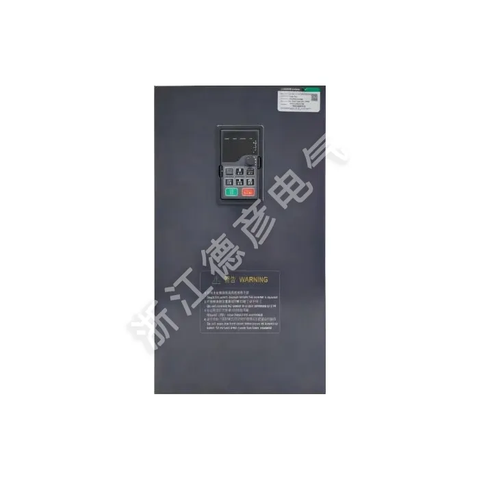
● Intuitive LED operator panel: The drive is equipped with 8 function keys, a 5-digit 7-segment LED display, and 5 status indicators. The menu structure is logically grouped, with CNC-specific parameters (acceleration/deceleration times, jog settings, and DC braking) easily accessible without digging through dozens of irrelevant options.
● Flexible frequency setting methods: Whether you prefer panel knob adjustment, analog voltage/current input from the CNC controller, multi-step speed selection, or RS485 communication, the drive supports all of these. This means you can use the method that best fits your existing control architecture without forcing a change in wiring.
● Parameter copying for multiple machines: If you have several machining centers with identical spindle setups, you can copy the parameter set from one drive to another via the communication port. This ensures consistent performance across your shop floor and drastically reduces setup time for fleet-wide upgrades.
With these design choices, a basic spindle drive setup—including motor parameter entry, speed reference configuration, and ramp time adjustment—can be completed in 15 to 20 minutes. Advanced tuning for closed-loop vector control may take additional time for encoder alignment, but the structured menu and comprehensive documentation make the process straightforward. Your engineers can focus on production, not on deciphering a poorly designed interface.
Talking to your CNC controller
Modern machining centers are rarely islands. They are connected to PLCs, HMIs, and often to factory-wide MES systems that track production metrics in real time. A drive that cannot communicate effectively becomes a blind spot—operators cannot monitor spindle status from the control panel, and diagnostic information is only available locally, slowing troubleshooting. The trend toward Industry 4.0 makes communication not a luxury, but a necessity.
Connectivity that fits your existing infrastructure:
1. Standard RS485 with Modbus protocol: Every drive comes with this as standard. You can read real-time parameters—output frequency, motor current, DC bus voltage, and even power factor—directly from your CNC controller or a supervisory system. Start, stop, and speed commands can also be issued remotely, eliminating the need for hard-wired analog signals that drift over time.
2. Real-time data for predictive maintenance: By continuously monitoring current and temperature data through the communication link, you can detect abnormal trends before they lead to failures, scheduling maintenance proactively rather than reacting to breakdowns.
3. Optional communication and PG cards: For applications that require other fieldbus protocols, optional isolated communication cards are available. Additionally, PG cards support multiple encoder types—differential, open-drain, UVW, and resolver—so you are not locked into a single feedback technology. This flexibility is critical when retrofitting older machines or integrating with different spindle motor brands.
Seamless communication eliminates the guesswork. You get full visibility into spindle performance, simplified integration with your automation ecosystem, and the freedom to choose the encoder that best fits your motor. No signal converters, no compatibility headaches—just plug-and-play connectivity that works.
Stopping fast and safely
In a machining center, rapid deceleration is just as critical as rapid acceleration. Tool changes demand that the spindle stops quickly to minimize non-cutting time. Emergency situations require a reliable stop to protect both the machine and the operator. Without adequate braking, a heavy spindle can coast for many seconds, wasting time and creating unnecessary safety risks. The braking system must be robust, configurable, and fail-safe.
Braking and protection features that deliver confidence:
● Configurable DC braking: You can set the braking frequency (from 0.00Hz to the maximum frequency), braking time (0.0 to 36.0 seconds), and braking current (0.0% to 100.0%). This allows you to match the braking profile exactly to your spindle's inertia and typical stopping requirements, whether you need a gentle deceleration for heavy chucks or an aggressive stop for quick tool changes.
● Integrated braking unit (22kW and below): For the majority of machining center spindles, the internal braking unit is more than sufficient. It saves panel space, simplifies wiring, and reduces overall system cost. The drive also includes over-voltage stall prevention, which actively manages the DC bus voltage during aggressive deceleration to prevent damage to the braking circuit.
● Comprehensive protection functions: Beyond braking, the drive offers overvoltage, overcurrent, overload, and overheat protection, all with configurable shutdown levels. It also includes motor short-circuit detection upon power-on and input/output phase-loss protection. These safeguards are not afterthoughts—they are integral to the drive's design, ensuring that faults are caught early and damage is prevented.
The result is a spindle that stops when you need it to, without drama or risk. Faster tool changes translate to shorter cycle times, and reliable emergency stopping ensures operator safety. Meanwhile, the comprehensive protection suite gives you peace of mind that your expensive spindle motor and drive are safeguarded against electrical and mechanical faults.
Real quality, real support
Specifications and features are essential, but the true value of a drive is revealed over years of operation in a demanding shop-floor environment. Reliability is not just about component ratings—it is about manufacturing consistency, thermal design, and the quality of every solder joint and capacitor. Behind every Deyan Electric Inverter Drive for CNC Machining Center Equipment is a manufacturing philosophy that prioritizes longevity and customer success.
What you can expect from Deyan Electric as a partner:
1. Manufacturing excellence: Based in Yueqing, Zhejiang—the heart of China's electrical industry—our facilities operate under strict quality control protocols. Every drive undergoes comprehensive factory testing, including full-load burn-in and communication verification, before it is shipped.
2. Component quality: We source premium-grade IGBTs and capacitors from established suppliers, and our thermal management design is validated to ensure continuous operation at ambient temperatures up to 40℃ (with derating capability up to 50℃). This means reliable performance even in poorly ventilated machine enclosures.
3. Environmental adaptability: The drive is designed for indoor use, with protection against dust, corrosive gases, and vibration up to 5.9m/s². It operates without performance degradation at altitudes below 1000 meters, and storage temperature ranges from -20℃ to 60℃—ready for any logistical condition.
4. Technical support and warranty: We offer comprehensive technical support for parameter tuning, application-specific configuration, and troubleshooting. Our warranty reflects our confidence in the drive's durability, and our team is responsive to inquiries, ensuring that you are never left to solve problems alone.
Choosing Deyan Electric means choosing a supplier that understands the real pressures of CNC production. We are not just selling a drive; we are providing a tool that enables your machinists to deliver better parts, faster, with less waste. That is the foundation of a partnership built on mutual success.
Frequently Asked Questions
Q: Is this drive compatible with both induction and synchronous reluctance spindle motors?
A: Yes. The drive supports standard induction motors in V/F, SVC, and FVC modes. For permanent magnet synchronous motors (PMSM), it is fully compatible in closed-loop vector control (FVC) mode with appropriate encoder feedback. You will need to enter the correct motor parameters (stator resistance, inductance, etc.) for optimal performance, but the drive supports this configuration.
Q: What is the maximum output frequency, and how does it translate to RPM?
A: The drive outputs up to 500Hz. For a standard 2-pole induction motor, 500Hz corresponds to 30,000 RPM (synchronous speed). For a 4-pole motor, it is 15,000 RPM. This range covers the vast majority of machining center spindle requirements, from heavy-duty low-speed applications to high-speed finishing.
Q: Can I use this drive with an analog speed command (0-10V) from my existing CNC controller?
A: Absolutely. The drive has two analog inputs: AI1 (0-10V) and AI2 (0-10V or 0-20mA, selectable). You can set AI1 as the main frequency source and configure the scaling to match your controller's output range. This ensures a drop-in replacement for older drives without rewiring your control panel.
Q: How do I know if the built-in braking unit is sufficient for my application?
A: For drives up to 22kW, the internal braking unit is designed for standard deceleration cycles typical of machining centers. If your application involves extremely high inertia (e.g., very large chucks or flywheels) or frequent, rapid stops (e.g., tapping cycles), we recommend evaluating the braking duty cycle. You can monitor the braking resistor temperature and, if necessary, add an external resistor with higher power rating. The drive has terminals for external braking resistors on larger models.
Q: Does the drive provide diagnostic information that can be accessed remotely?
A: Yes. Via the RS485 port and Modbus protocol, you can read fault codes, current, voltage, temperature, and a wide range of operational parameters. This allows you to build a remote monitoring dashboard or integrate the drive into your predictive maintenance system, helping you catch issues before they cause downtime.
Q: What happens if the plant voltage drops unexpectedly?
A: The drive's automatic voltage regulation (AVR) compensates for input voltage fluctuations, maintaining stable output voltage to the motor. Additionally, the momentary power failure ride-through function allows the drive to continue operating for a short period during brief interruptions, preventing spindle coast-down and ensuring that you can resume cutting without restarting the entire cycle.
Q: How long is the typical service life of this drive in a CNC environment?
A: With proper installation (adequate cooling, clean power, and correct parameter settings), these drives typically exceed 10 years of service life. The use of high-grade electrolytic capacitors and robust power modules, combined with comprehensive protection circuits, ensures that the drive withstands the thermal and electrical stresses of daily machining operations.