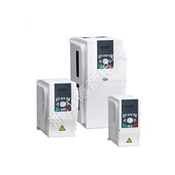
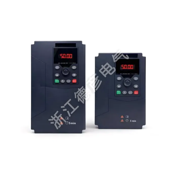
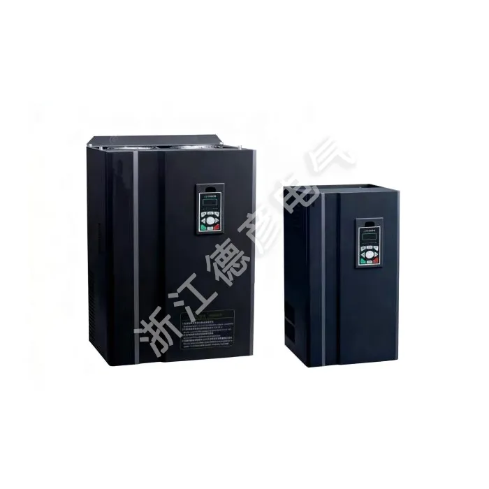
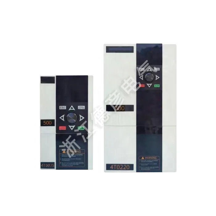
Sourced from a professional China manufacturer, the Variable Frequency Inverter for Fan Pump Applications covers power ratings from 0.75kW up to 400kW, built specifically for square‑law loads found in water boosting, HVAC ventilation and wastewater pumping. A great number of existing facilities burn excess energy by throttling flow with dampers and valves while motors run full‑speed. This LNC820 drive solves real‑site pain points including pipe water hammer, pressure fluctuation, frequent unit tripping and high ongoing power bills for retrofit jobs and OEM system builders across global markets.
Many mechanical contractors learn through hands‑on jobs that slapping a standard general‑purpose VFD onto fan or pump equipment does not always deliver stable outcomes. General‑purpose drives are tuned for constant‑torque machinery; they lack the built‑in logic that fan‑pump systems actually require. After years of shipping drive units for on‑site retrofits worldwide, Deyan Electric developed the Variable Frequency Inverter for Fan Pump Applications around real‑world feedback from installers, maintenance crews and end‑plant operators. Every unit undergoes square‑law load simulation on test benches and continuous aging before shipment. It is not just another speed‑control device; it is configured out‑of‑the‑box to handle the unique behaviors of centrifugal fans and centrifugal pumps without heavy parameter rewriting on‑site.
Common Headaches Seen On Fan‑Pump Job Sites
Energy saving is the main reason most customers look for fan‑pump inverters, yet many projects run into unexpected snags after hardware is mounted in cabinet. These recurring field issues rarely show up on datasheets, but they decide whether your installation runs reliably month after month:
1. Water hammer damage from abrupt pump speed shifts: Fast ramp‑up or ramp‑down sends shockwaves through pipe networks. Seals, pipe joints and check valves take repeated impact, leading to leaks and more frequent maintenance work. This drive features adjustable soft acceleration and deceleration curves to smooth pressure changes inside piping.
2. Pressure hunting in large pipe networks: Big water supply systems carry large fluid inertia. Generic VFD PID settings often make pressure swing back and forth, never locking onto the set target. Pre‑loaded fan‑pump PID baselines cut down hours of trial‑and‑error tuning work for installers.
3. False tripping during off‑peak low‑load periods: In residential water booster stations, water demand drops late at night. Some drives struggle running under very light square‑law load and trigger over‑current or under‑voltage faults. Optimized firmware stabilizes operation under minimal‑flow conditions.
4. Motor overheating risk at sustained low‑speed operation: Fan‑pump motors cool themselves via shaft‑mounted fans. Long‑time low‑rpm running reduces self‑cooling airflow. Operators get warning prompts so they can avoid motor burnout caused by prolonged low‑frequency running.
It is worth noting these problems are seldom hardware defects; most stem from using drives not optimized for square‑law fan‑pump characteristics.
Why P‑Type Fan‑Pump Drive Differs From Heavy‑Duty G‑Type Units
Buyers frequently ask: can I just order G‑type heavy‑duty inverters for fan and pump projects? It will spin the motor, but you pay extra for overload capacity you will almost never use on centrifugal fan‑pump loads. The Variable Frequency Inverter for Fan Pump Applications adopts P‑type rating purpose‑matched for square‑law profiles:
1. P‑type overload rating fit for fan‑pump startup surge: 130% rated current for 60 seconds. Centrifugal fans and pumps only draw higher current briefly at startup, no need for 150% heavy‑duty constant‑torque margin. This keeps material cost lower without sacrificing operational reliability.
2. Native sleep‑wake logic for low‑demand idle conditions: When water consumption stays extremely low for extended time, the drive can stop the pump automatically. It restarts once pipeline pressure falls below preset threshold. Widely used for building water booster systems, avoids useless pump idling in midnight low‑demand hours.
3. Multi‑pump group switching without extra expansion cards: Combined with onboard simple PLC logic and terminal signal configuration, one inverter can sequence multiple pumps in turn. Helps large pump stations balance service hours across the whole pump bank, reduces wear concentrated on single equipment.
4. Pre‑configured PID parameter groups for pressure / airflow stabilization: Installers do not need to start PID tuning completely blank. Technicians adjust a small number of parameters based on actual pipe size and site conditions, shortening cabinet commissioning cycles.
All these functions run inside original firmware, no additional option boards needed, helping keep control cabinet layout tidy and lower overall project BOM cost.
On‑Site Installation & Common Mis‑configuration Pitfalls
Even well‑designed VFD hardware will under‑perform or trip unexpectedly if field wiring, sensor placement and parameter setup are not handled properly. Below are practical notes collected from hundreds of overseas fan‑pump retrofit cases:
1. Sensor mounting location directly impacts PID stability: Pressure or flow transmitters should install on straight stable pipe sections. Keep sensors away from elbows, tees and valve locations. Turbulent flow creates noisy feedback signals, resulting in continuous pressure oscillation no matter how you tweak PID gains.
2. Set hard minimum running frequency limit for pumps: Avoid long‑time operation below 20% rated speed. Ultra‑low flow causes internal pump recirculation, poor lubrication and mechanical damage. Lock lower‑frequency threshold in drive parameters to protect pump hardware.
3. Inverter soft ramp cannot eliminate water hammer entirely: Soft start‑stop eases pressure shock but works together with mechanical check‑valve performance. Match acceleration‑deceleration timing with valve closing speed for best pipe‑network protection effect.
4. Do not apply P‑type model for positive‑displacement equipment: P‑type is made for centrifugal fans and centrifugal pumps. For roots blowers, rotary lobe pumps with heavy starting torque, select G‑type heavy‑duty variant even though it belongs to fan‑pump‑related machinery.
Following these practical guidelines helps integrators steer clear of most post‑installation complaints before they occur.
Factory Testing & Buyer‑Oriented Project Support
At production stage, this fan‑pump specific inverter goes through more than basic motor rotation testing. Our test bench simulates square‑law load conditions, validating sleep‑wake trigger thresholds, multi‑pump switching sequence and closed‑loop PID stability before product leaves factory floor.
1. Application‑oriented aging test: Each finished unit runs simulated fan‑pump duty cycle during aging process, not just simple no‑load running. Catch firmware‑related abnormalities ahead of delivery.
2. Specialized commissioning guidance inside user manual: Dedicated chapters cover sleep‑wake setup, PID tuning tips and multi‑pump cascade configuration, supporting overseas engineering teams to shorten debugging lead‑time.
3. Flexible order volume support: Complete power range 0.75kW‑400kW available, supporting small sample trial orders and large‑volume project bulk supply for system contractors and machinery OEM partners.
4. Remote technical troubleshooting backup: When installers face pressure instability, sleep‑wake failure or unexplained tripping after site installation, technical team provides remote guidance for parameter diagnosis and adjustment.
Pre‑shipment application‑focused testing lowers debugging risk for fan‑pump renovation projects.
Where This Fan‑Pump VFD Gets Put Into Real Service
This inverter fits both brand‑new system builds and legacy equipment retrofits. It delivers the greatest practical value in sites where flow, pressure or air volume keeps changing day and night:
1. Commercial & residential building constant‑pressure water boosting: Apartment blocks, office complexes and factory workshop water supply. The Variable Frequency Inverter for Fan Pump Applications modulates pump speed following real‑time water usage, maintains stable pipeline pressure and cuts power waste compared with old‑style pressure tank control schemes.
2. Industrial workshop ventilation and exhaust systems: Factory exhaust fans adjust air volume responding to temperature, dust or gas sensor feedback. Instead of mechanical damper throttling, motor speed adjusts dynamically. It reduces mechanical wear on dampers while trimming monthly power expenses.
3. Sewage and wastewater treatment pump stations: Incoming sewage volume fluctuates irregularly. Variable‑speed operation matches pump output to actual inflow, avoids frequent start‑stop cycles that quickly wear pump impellers and shaft seals.
4. Circulating water and farm irrigation systems: Factory cooling circulation loops, agricultural water irrigation projects. Flow requirements shift with production schedules or weather conditions. Speed regulation reduces idling power loss and stabilizes overall system performance.
If your fan or pump rarely needs to hold full‑speed operation around the clock, this drive brings tangible energy savings and extends mechanical service life of rotating equipment.
FAQ
Q: Can I use G‑type heavy‑duty VFD for centrifugal fan and pump?
A: It can drive the motor physically, yet G‑type carries higher cost and surplus overload margin which centrifugal fan‑pump loads almost never require. Standard centrifugal fan‑pump applications should pick cost‑optimized P‑type. For positive‑displacement blowers and rotary pumps with heavy startup torque, choose G‑type heavy‑duty model.
Q: What real‑world energy saving percentage can I get for fan‑pump retrofit?
A: Energy saving result depends heavily on actual working cycles. When flow demand varies significantly, savings can hit 20‑50%. If equipment keeps running near full‑load most time, energy‑saving gain stays limited. Analyze on‑site operating condition before order placement.
Q: Does sleep‑wake function need extra option card purchase?
A: Sleep‑wake function is built‑into native firmware, no additional hardware purchase required. You only need configure sleep pressure threshold, sleep delay and wake‑up pressure value according to actual pipe‑network characteristics.
Q: Pump generates obvious vibration after VFD installation, what should I check?
A: Verify whether running frequency falls into mechanical resonance zone of pump‑pipe assembly. Set skip‑frequency parameters inside inverter to bypass resonance points. Meanwhile check sensor signal interference and mechanical fixing status of pump unit itself.
Nameplate Reference
|
MODEL:
|
LNC820‑4T0040GB/4T0055PB
|
|
POWER:
|
4KW 9A/5.5KW 13A
|
|
INPUT:
|
3PH AC380V 50HZ/60HZ
|
|
OUTPUT:
|
3PH AC0V‑380V 0HZ‑500HZ
|
|
S.N:
|
Barcode
|
Full Technical Specification
|
Item
|
Specification
|
|
Basic functions
|
Output frequency
|
0‑500Hz
|
|
Carrier frequency
|
0.8kHz~12kHz the carrier frequency can be automatically adjusted according to the load characteristics
|
|
Frequency resolution
|
0.01Hz
|
|
Control mode
|
V/F control
|
|
Torque characteristics
|
With torque compensation and slip compensation,starting torque: G‑type machine 0.5Hz/150%,P‑type machine 0.5Hz/100%
|
|
Torque boost
|
Automatic torque boost;Manual torque boost 0.1%~30.0%
|
|
Overload capacity
|
G‑type machine:150%of rated output current for 60S P‑type machine:130%of rated output current for 60S
|
|
Speed regulation range
|
1:100
|
|
Speed stability accuracy
|
±1%
|
|
Automatic voltage regulation(AVR)
|
When the grid voltage changes,it can automatically maintain a constant output voltage
|
|
Over‑voltage and over‑current stall control
|
Automatically limits the current and voltage during operation to prevent frequent over‑current and over‑voltage tripping
|
|
Fast current‑limiting function
|
Minimizes over‑current faults to protect the normal operation of the frequency converter
|
|
V/F curve
|
Four modes:linear type;multi‑point type;complete V/f separation;incomplete V/f separation
|
|
Acceleration and deceleration curves
|
Linear or S‑curve acceleration and deceleration modes;four acceleration and deceleration times; acceleration and deceleration time range:0.1~6500.0s
|
|
DC braking
|
DC braking frequency:0.00Hz~maximum frequency,braking time:0.0s~36.0s, braking action current value:0.0%~100.0%
|
|
Simple PLC,multi‑ speed operation
|
Jog frequency range:0.00Hz~50Hz;jog acceleration and deceleration time:0.0s~6500.0s
|
|
Jog control
|
Up to 16‑speed operation can be achieved through the built‑in PLC or control terminals
|
|
Built‑in PID
|
It can easily implement a process‑control closed‑loop control system
|
|
Operating characteristics
|
Operating command channel
|
Three channels:given by the operation panel,given by the control terminals,given by the serial communication port.It can be switched in various ways
|
|
Frequency source
|
Ten frequency sources:given by panel knob,given by operation panel,given by analog voltage, given by analog current,given by RS485 communication,multi‑speed,PID,simple PLC, which can be switched in various ways
|
|
Auxiliary frequency source
|
Ten auxiliary frequency sources.It can flexibly achieve auxiliary frequency fine‑tuning and frequency synthesis
|
|
Input terminals
|
Six digital input terminals,one of which can be used as a high‑speed pulse input. Two analog input channels,AI1:input range 0~+10V,AI2:input range 0~+10V/0‑20mA
|
|
Display and keyboard operation
|
Output terminals
|
One high‑speed pulse output terminal,outputting square‑wave signals from 0kHz~50kHz which can realize the output of physical quantities such as set frequency and output frequency. One digital output terminal. One relay output terminal. Two analog output terminals,AO2:0V~10V, AO1:0V~10V/0‑20mA,which can indicate output frequency/current/voltage/frequency command/ speed/power factor signal output
|
|
LED display
|
It is equipped with 8 function keys,a 5‑digit 7‑segment LED,and 5 status LED indicators. It can perform forward rotation,reverse rotation,reset,stop,jog,as well as parameter setting and display
|
|
Protection characteristics
|
Protection function
|
Motor short‑circuit detection upon power‑on,output phase‑loss protection,over‑current protection,over‑voltage protection,under‑voltage protection,over‑heat protection,overload protection,etc
|
|
Environment
|
Application place
|
Indoors,not directly exposed to sunlight,free from dust,corrosive gases,flammable gases,oil mist, water vapor,dripping water or salt,etc
|
|
Altitude
|
Less than 1000m
|
|
Ambient temperature
|
‑10℃~+40℃(When the ambient temperature is between 40℃~50℃,derating operation is required)
|
|
Humidity
|
Less than 95%RH,without water droplet condensation
|
|
Vibration
|
Less than 5.9m/s²(0.6g)
|
|
Storage temperature
|
‑20℃~+60℃
|