Introduction: The Importance of Scientific Selection and Common Pitfalls
In modern power systems, distribution transformers serve as indispensable core equipment, performing critical functions such as voltage conversion, power distribution, and system interconnection. A properly selected transformer not only ensures stable grid operation but also significantly reduces operational costs and enhances energy efficiency. However, in actual engineering practice, issues arising from improper selection are all too common.
Many procurement decision-makers fall into two extremes: first, overemphasizing overload capacity leads to selecting undersized transformers, causing prolonged overloading that shortens equipment lifespan or triggers failures; second, misjudging operational conditions results in oversized transformers, wasting initial investment and causing persistently high no-load losses over time. Complicating matters further, transformer selection involves not only electrical parameters but also comprehensive considerations across multiple dimensions, including materials science, structural design, and operational economics.
This article systematically outlines the selection principles for distribution transformers based on practical engineering requirements. It covers capacity calculation, number determination, type selection, structural design, and core material technology, providing a comprehensive and practical selection framework for power engineers, procurement decision-makers, and technical managers.Chapter 1: Scientific Determination of Transformer Capacity and Number
1.1 Basic Principles for Capacity Selection
Transformer capacity selection should adhere to the core principle of “approximate capacity, slightly exceeding calculations.” For permanent power supply systems, such as the national grid, the economic load factor of transformers is typically maintained between 60% and 70%. In practical engineering, the rated capacity of transformers is generally selected as 1.15 times the calculated load. This approach satisfies peak load demands while avoiding efficiency losses caused by prolonged underloading.
Critical Constraint: The capacity of a single distribution transformer should generally not exceed 1000kVA. If load demand surpasses this limit, consider employing multiple transformers in parallel operation. This approach not only enhances power supply reliability but also allows decommissioning some transformers during light-load periods to reduce losses.
1.2 Capacity Calculation for Different Application Scenarios
1.2.1 Main Transformers in Power Plant Unit Wiring
When generators and transformers employ a one-to-one unit wiring system, the main transformer capacity must satisfy the following condition:
- Calculation formula: \( S_{TN} > (S_{GN} - S_C) / 0.9 \)
Where \( S_{GN} \) is the generator rated capacity, \( S_C \) is the plant auxiliary load of the unit, and division by 0.9 indicates reserving approximately 10% capacity margin.
- Standard Matching: In practice, main transformer capacity is typically selected to match generator capacity. For example:
- 200MW unit (235MVA) paired with 240MVA main transformer
- 300MW unit (353MVA) paired with 360MVA main transformer
- Expanded Unit Connection: When two generators share a transformer, split-winding transformers are preferred. Capacity is determined by summing the capacities required for each unit according to unit connection principles. This design effectively limits short-circuit currents and enhances power supply reliability.
1.2.2 Main Transformers with Generator Voltage Busbars
This configuration is common in power plants with organic-end loads. Capacity determination requires verification through multiple operational scenarios:
1. Minimum machine-end load condition: Ensure all remaining generating power can be transmitted
2. Maximum single-unit outage condition: The system must be capable of transferring power via main transformers to meet maximum machine-end load demand
3. N-1 security verification: When any main transformer is withdrawn, the remaining transformers must deliver at least 70% of the residual power within their permissible overload range
4. Special system requirements: For systems with high hydroelectric proportion, thermal power plant main transformers must have the capability to reverse-feed the generator terminal base load
Calculation example: A power plant has two generators (50MW + 25MW), with a maximum generator terminal load of 70MW (including plant auxiliary power). During normal operation, it supplies 5MW to the system. When the larger generator (50MW) undergoes maintenance, 45MW must be reverse-fed from the system. The main transformer capacity must at least meet this 45MW reverse-feeding requirement.
1.2.3 Capacity Selection for Interconnection Transformers
Interconnection transformers connect power grids of different voltage levels. Their selection requires special consideration:
- Number Restriction: Typically one unit, maximum two units, to simplify layout and busbar connections
- Capacity Principles:
1) Meet power exchange requirements between the two voltage networks under all operational modes
2) Capacity must not be less than the largest unit connected to either voltage busbar, ensuring load demand is met via the interconnection transformer during unit failure
1.2.4 Planning Selection of Main Transformers for Substations
Main transformer capacity selection requires forward-looking planning:
- Planning horizon: Generally determined based on 5-10 year load growth projections
- Reliability requirements: When one main transformer is out of service, the remaining transformers must meet the power supply needs of Class I and II loads (typically accounting for 70%-80% of total load) while accounting for overload capacity
- Number of Transformers:
- Large/medium power plants and hub substations with strong grid connections: At least 2 units per voltage level
- Small/medium power plants with weak grid connections or substations at 10kV and below: May install only 1 unit- Regional isolated substations or large industrial dedicated substations: May consider a 3-unit main transformer configuration
Chapter 2: Selection of Transformer Type and Structure
2.1 Selection of Phase Number and Number of Windings
- Phase number selection: Three-phase transformers are preferred for voltage levels of 330kV and below; for 500kV and above, single-phase transformer banks may be considered based on transportation conditions and system requirements.
- Number of Windings Principle: Three-winding transformers are preferred unless the sustained power flow through any single winding is projected to be less than 15% of the transformer's rated capacity.
2.2 Selection of Structural Type
- Advantages of autotransformers: When both voltage levels of the grid employ high-current grounded systems, autotransformers should be prioritized. Their low losses, compact size, and high efficiency make them particularly suitable as interconnection transformers for high/medium voltage sides. The low-voltage winding can also serve as a plant standby power source or connect to a synchronous condenser.
- Applications of split-phase transformers: Suitable for expanding unit connections and scenarios requiring short-circuit current limitation
2.3 Winding Connections and Voltage Regulation Methods
- Connection group: Must align with system voltage phase, with at least one winding connected in delta configuration to eliminate third-harmonic effects
- Voltage Regulation Methods:
- Conventional tap changer regulation: Preferred when power flow variations are minimal
- On-load tap changer (OLTC): Considered only when load fluctuations are severe and secondary voltage cannot meet requirements; offers flexible regulation despite higher cost
2.4 Selection of Cooling Method
Choose an appropriate cooling method based on the installation environment, transformer type, and capacity:
1. Natural Air Cooling: Suitable for small, low-loss transformers
2. Forced Air Cooling: Commonly used for medium-capacity transformers3. Forced Oil Circulation Cooling: Includes water-cooled, air-cooled, and guided cooling; suitable for large, high-power-density transformers
Chapter 3: Technical Considerations for Core Materials
The heart of a transformer lies in its core, whose performance is primarily determined by the silicon steel sheets used. Understanding material properties is crucial for selecting efficient, energy-saving transformers.
3.1 Fundamentals of Silicon Steel Sheets
Silicon steel sheets, also known as electrical steel, are the core material for manufacturing transformer cores. Classified by grain orientation:
- Grain-oriented electrical steel (GOES): Grains highly oriented along the rolling direction with uniform magnetization, offering high permeability and low iron loss, particularly suitable for transformers
- Non-grain-oriented electrical steel (NGOES): Randomly oriented grains with isotropic magnetic properties, primarily used in rotating electrical machines
3.2 Key Performance Indicators for GOES
3.2.1 Magnetic Properties Parameters
- High permeability: Ensures magnetic field passage with minimal resistance, enhancing conversion efficiency
- Low coercivity: Reduces energy loss during magnetization cycles
- Typical high-efficiency grades:
- 27QG110 (Baosteel, China)
- 23RK80
- 20RK65
3.2.2 Iron Loss Characteristics
Iron loss is a key metric for transformer no-load losses, comprising hysteresis loss and eddy current loss:
- Low-loss grades:
- 27Q120 (Baosteel)
- 23Q85
- 30P110 (POSCO)
3.2.3 Thickness vs. Performance Balance
Silicon steel sheet thickness typically ranges from 0.18 to 0.35 mm:
- Advantages of thin gauges: 0.18–0.23 mm sheets significantly reduce eddy current losses
- Processing challenges: However, thinner materials are harder to process, increasing stamping costs
- Cost-effective choice: 0.27–0.30 mm offers a good balance between performance and cost
3.3 Importance of Insulation Coating
High-quality silicon steel sheets feature specialized insulation coatings with multiple functions:
1. Prevents interlayer short circuits and reduces eddy current losses
2. Enhances heat resistance and oxidation resistance, extending service life
3. Minimizes die wear during punching and shearing processes
4. Meets environmental standards (low VOC, heavy metal-free)
3.4 Special Requirements for Thermal Stability
For transformers operating in harsh environments (e.g., deserts, high altitudes, high-temperature industrial settings), select silicon steel grades with superior thermal stability:
- 27QH100 (Baosteel)
- M103-27P5 (JFE)
- 27PG110 (POSCO)Chapter 4: Selection Strategies for Special Application Scenarios
4.1 Rural Grids and Seasonal Loads
Rural grids and seasonal industrial loads exhibit significant peak-to-valley differences, requiring specialized considerations:
- Recommended Approach: Employ “master-slave transformer” or parallel transformer operation
- Operational Strategy: Flexibly switch transformers based on actual load variations, adhering to the principle of “minimum energy loss”
- Capacity Configuration: Main transformer covers base load; auxiliary transformer handles seasonal peaks
4.2 Industrial Dedicated Substations
Key considerations for selecting transformers in large industrial enterprise substations:
- Harmonic impact: High harmonic content in metallurgical, chemical, and similar loads requires transformers with strong harmonic resistance
- Impact loads: Equipment like rolling mills and electric arc furnaces generate impact loads; transformers must have sufficient overload capacity and mechanical strength
- Environmental Adaptability: Corrosion and moisture resistance designs are essential for chemical plants and coastal regions
4.3 Renewable Energy Integration Scenarios
Transformer selection for renewable energy sites like PV plants and wind farms:
- Volatility Adaptation: Must withstand rapid power fluctuations
- Low Load Factor Operation: Optimize efficiency in low-load zones due to intermittent renewable generation
- Bidirectional Power Flow: Distributed PV may feed power back into the grid; transformer design must account for bidirectional operation Chapter 5: Economic Analysis and Full Life Cycle Cost Assessment
5.1 Balancing Initial Investment and Long-Term Operating Costs
Transformer selection should not focus solely on purchase price but comprehensively consider:
- Payback period for premium-priced high-efficiency transformers: Typically recouped through energy savings within 3-5 years
- Loss assessment: Calculate total loss costs over the transformer's expected lifespan (typically 20-30 years)
- Maintenance costs: Variations in maintenance requirements and expenses across different transformer types
5.2 National Standards and Energy Efficiency Requirements
- China's energy efficiency standards: Adhere to GB 20052 “Limiting Values and Grades of Energy Efficiency for Power Transformers”
- International standards: Understand relevant IEC and IEEE standards, particularly for export projects
- Environmental Requirements: Focus on transformer oil's environmental performance and recycling/disposal requirements
5.3 Supplier Evaluation and Technical Audit
Considerations when selecting transformer suppliers:
1. Technical Capability: Design experience, R&D strength, quality control systems
2. Performance References: Successful case studies from similar projects
3. After-Sales Service: Technical support, spare parts supply, maintenance response
4. Sustainability: Environmental philosophy, material recyclabilityChapter 6: Modern Technology Development Trends
6.1 Digitalization and Intelligence
- Online Monitoring Systems: Integrated sensors for temperature, oil chromatography, partial discharge, etc.
- Condition Assessment and Predictive Maintenance: Lifespan prediction based on big data analysis
- Intelligent Voltage Regulation: Automatic voltage adjustment combined with load forecasting
6.2 New Material Applications
- Amorphous Alloy Transformers: Extremely low no-load losses, suitable for low-load-factor scenarios
- High-temperature superconducting transformers: Potential revolutionary transformation of transformer design in the future
- Eco-friendly insulation materials: Natural ester insulating fluids, biodegradable materials
6.3 Modular and Standardized Design
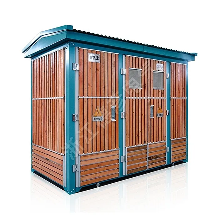
- Prefabricated substations: Factory-integrated, rapid on-site installation
- Standardized interfaces: Facilitates upgrades, replacements, and system expansion
- Compact design: Space-saving, particularly suitable for urban grid retrofits
Conclusion: A Systematic Selection Decision Framework
Selecting the appropriate distribution transformer involves a multi-objective, multi-constraint systems engineering decision process. The ideal selection should follow this decision path:
Step 1: Requirements Analysis
- Define load characteristics (size, curve, harmonics, impact)
- Determine system connection requirements (voltage level, wiring configuration)
- Evaluate operating environment (temperature, humidity, altitude, pollution level)
Step 2: Capacity and Unit Quantity Determination
- Based on load calculations and N-1 reliability criteria
- Consider near-term demand and long-term expansion
- Balance reliability and economic efficiency
Step 3: Technical Specification Development
- Select transformer type (phase configuration, windings, structure)
- Define performance parameters (impedance, losses, temperature rise, noise level)
- Specify special requirements (on-load tap-changing, sealing, corrosion resistance)
Step 4: Material and Process Selection
- Core silicon steel sheet grade and thickness
- Winding conductor material and insulation system
- Cooling method and noise reduction measures
Step 5: Economic Evaluation
- Compare initial investment costs of different solutions
- Calculate total lifecycle costs (energy consumption, maintenance, decommissioning)
- Assess supplier's overall capabilities
Step 6: Sustainability Considerations
- Energy efficiency ratings and environmental impact
- Material recyclability and eco-friendly disposal
- Technological Advancement and Future Adaptability
Through this systematic framework, decision-makers can avoid common selection pitfalls, ensuring the chosen transformer not only meets current technical requirements but also delivers reliable, efficient, and economical service for decades to come. Against the backdrop of energy transition and digital transformation, the selection of distribution transformers has evolved from a simple equipment procurement into a critical strategic decision impacting the efficiency and safety of the entire power system.
As new materials and technologies continuously emerge, the knowledge base for transformer selection is constantly evolving. It is recommended that engineering and technical personnel maintain ongoing learning, track the latest industry developments, and engage in thorough communication with equipment manufacturers, design institutes, and operating units during specific projects. This collaborative approach will ultimately lead to scientifically sound and reasonable selection decisions, laying a solid foundation for building a safe, efficient, and green modern power system.
Address:No.60, Binhai South Second Road, Economic Development Zone, Yueqing City, Zhejiang Province, China
Copyright © 2025 Zhejiang Deyan Electric Co.,Ltd. All Rights Reserved. Links| Sitemap| RSS| XML| Privacy Policy